The project I will work on using OnShape is a omnidirectional gear that I plan to 3D print using my SLA printer.
About OnShape
OnShape is an online 3D modelling software that is ideal for collaborating on a project. It is not the most rigorous CAD tool, but there is a free version and it is quite user intuitive.

Furthermore, it has several usefull libraries such as the Beam add-on for quickly creating 8020 extrusions. Its online and open model has enabled a lot of interesting development and add-ons such as this.

It has the ability to model indivdual parts and/or create assemblies. It also has great version control and the ability to import and export files as STEP, STL, 3mf (Fusion 360), and .sldprt (Solidworks), and Rhino. This makes it a great place to store your modelling files on a project where you have multiple designers who use different softwares.


I definitely recommend OnShape for a beginner modeller who is looking for a simple user interface and wants to collaborate on a team project. Or as a nice PLM or ECO management for your CAD files for advanced designers who want to collaborate on a team across CAD softwares.
Project 1 - Spherical gear
Modeling Workflow
For this project I am going to create an omnidirectional actuveball mecahnism joint (more commonly known as a “Spherical gear”) to print on my SLA printer. I want to make this to test the abilities of this type of joint for motion control. The GIF below demonstrates the functionality of what I will be modelling.

I am printing it on my SLA printer so that I can test SLA printing parameters and get an idea for how well it is capable of printing something like this that requires a bit of a smooth surface finish compared to what a FDM printer might be capable of doing in the same amount of print time.
1. Create new project folder and file
To begin I created a new project folder because the joint will consist of numerous parts. From a documentation and version control perspective it makes most sense to save all the files in one folder. After thisyou can create a new document. I am calling the folder “omnigear” and the document “driven-sphere”.

Once you have created your file you will enter into a regular workspace where you can select your plane and begin modelling.

2. Add the spur gear tool
To begin modelling this part I’m actually going to use the spur gear tool offered by OnShape to generate my spur gear sketch and then revolve it around the x-axis and then do a revolved cut around the y-axis to design my part. To add the spur gear tool navigate to the “Search tools” button or press alt-c. Then type gear into the search bar. Click on it and it will generate a gear part.

3. Set the gear parameters
Once complete, you can very easily modify the gear specifications, including the depth (thickness of the gear), number of teeth, Pitch circle diameter, the pressure angle, root fillet, and you can even create helical gears and center boards by checking the boxes. For my model I am going to create a 5 cm (50 mm) diameter spherical gear with 35 teeth and a thickness of 5 mm. Once you have modified the given parameters click on the green arrow to generate the part.

4. Project the gear onto a new sketch midplane
The Next step is to create a new sketch on the front plane, by selecting it, and clicking the sketch button on the top left. Next. we will click on the “Use” button and select the gear body. This will project the gear onto the midplane.

5. Cut half the gear away on the sketch and revolve the gear
The next step is to draw a line across the center of the gear and delete one half of it so we can revolve it around its center axis.


You should end up with something similar to the below.

6. Copy the spur-gear sketch onto the right plane
The final step is to open the spur-gear sketch that was cut. You can then copy the sketch and create a new sketch on the right plane and paste the sketch features. Next transform the sketch so that it intersects with the revolve tooth. As per the images below.


Next, create a centerpoint arc that goes around the outside of the gear and connect it all to the gears so you will remove the correct material.

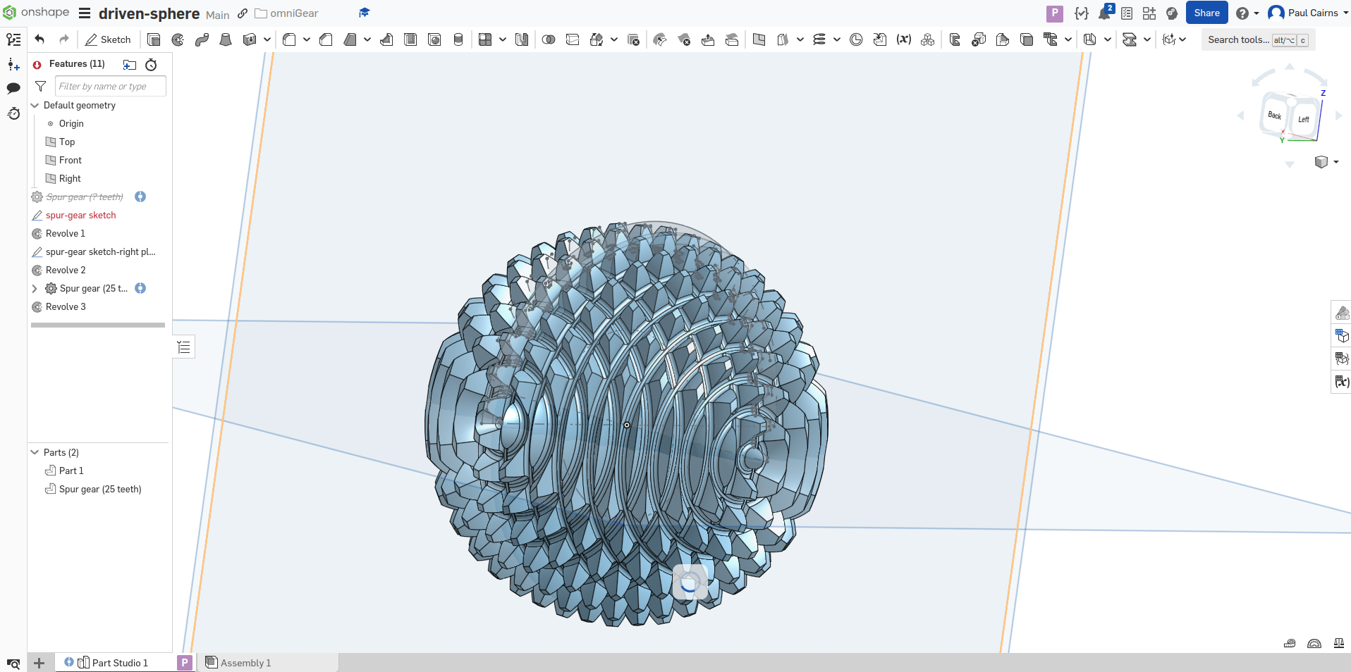
7. Perform a revolve cut to finish the piece
Use the revolve feature once again and select the “Remove” option to cut away the transformation.

You should end up with something that looks like the following below.

8. Export STL to import into your favorite slicer for 3D printing
Export the STL file for your slicer and enjoy.


Project 2 - Spiral Tree
I saw this interesting project on Twitter/X and wanted to challenge myself if I could recreate it just by looking at the final project. Below is a video of what I wanted to model.
The originaL post is available here
Modelling workflow
Below are the steps I took to make the two parts.
1. Create new project folder and new files for each part
I started by creating a new project folder and then created new project files, on for each part. This will help with version control later. Note that my typical approach to PDM is to have each system as its own project file with its sub-assemblies as seperate tabs and one tab for full assembly. With this project each part is its own system, which is why they each received their own project file

I started first with modelling the female part
2. Revolve feature for both parts
I started by making the general cone from which I am going to do a sweeping cut of the star that I will draw on the base of the cone. I started first by drawing the cross-section of the cone. Followed by revolving about the z-axis


This was repeated for the male part as well. Next was the helix
3. Helix feature for both parts
I used the helix feature with the base as the reference geometry. Since it will be a six pointed start, there will be 6 thread tracks per revolution. As a result I used a half of a revolution over the length to give the effect of three full turns.

Once the helix was defined the next step was to create the star sketch on the base.
4. Creating the profile for the Sweep cut
The next step was to create the profile for the sweep cut. To do this, I needed to draw a six pointed star. I defined the star by creating two construction circles with all points of the star coincident on each and all sides of the star equal. For the male star, I made it 0.2 mm smaller on both dimensions so it would fit inside the female star.


For the male sketch there was a circle on the outside as we would be removing material.
5. Sweep cut for both parts
The next step was the sweep cut. With Onshape, you use the “Sweep” feature and select the “remove” tab in the feature details section. Then you select the sketch and profile. I used the star sketch and the helix as the profile. Below are the results for the male and female parts. Seperately.


Lastly was the fillet of the male part.
6. Fillet of male part
The last step was to do a fillet on the male part. To do this I selected the fillet feature and the top face. I used a fillet radius of 3 mm.

7. Version control
I also decided to do some version control using OnShapes PDM features. With it you are able to create different versions and branches of a part. You can also merge features. Lastly, you can select whether it is a version, for release, or release. Some very interesting features are included with this software.

8. Result
After I finished the parts I exported them and printed them on my SLA printer. Below is an image of the slice in the AnyCubic Photon software and a video of the result.
