Background information
The objective of this project was to learn how to program a 6 DOF robot arm to be used as a pick and place (PnP) machine using computer vision. To do this, I used an off the shelf 6DOF robotic arm that I bought on Amazon called, “LeArm”. I started by assembling and learning the hardware/mechanics. Next, I had to learn some background information about how to kinematicly define and program the robot arm.
The following sections will go over the specifications of LeArm, and provide background about Denavit-Hartenberg frames and coordinate systems.
Specifications of LeArm
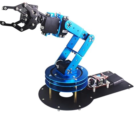
For this project I used LeArm 6 DOF robot kit as an off the shelf robot arm. It is programmable and controllable. I would like to tie it with a computer vision AI program to recognize little cubes, calculate their coordinates, move to that position to grab the cube, and then place the cube in a little basket.
Below are the details and specifications for LeArm.
ADD DETAILS HERE
Denavit-Hartenberg Frames and Coordinate Systems
To begin, the first thing is to understand and learn D-H frames and coordinate systems for mechanisms.
Below is text taken from automaticaddison describing D-H coordinate systems and their rules. You can find the full article here. I suggest you read take a look as it is very detailed, and valuable information to know.
Denavit-Hartenberg (D-H) frames help us to derive the equations that enable us to control a robotic arm.
The D-H frames of a particular robotic arm can be classified as follows:
- Global coordinate frame: This coordinate frame can have many names…world frame, base frame, etc. […]
- Joint frames: We need a coordinate frame for each joint.
- End-effector frame: We need a coordinate frame for the end effector of the robot (i.e. the gripper, hand, etc….that piece of the robot that has a direct effect on the world).
The other important information to know about D-H coordinate frames are the four rules for defining the D-H convention in a mechanical system and kinematic drawing. These rules are important to ensure that a 6 DOF robot is properly defined and easily programmable. Again the following text is taken directly from the automaticaddison.com article.
Here are the four rules that guide the drawing of the D-H coordinate frames:
- The z-axis is the axis of rotation for a revolute joint.
- The x-axis must be perpendicular to both the current z-axis and the previous z-axis.
- The y-axis is determined from the x-axis and z-axis by using the right-hand coordinate system.
- The x-axis must intersect the previous z-axis (rule does not apply to frame 0).
Below is an example for how to draw the D-H frames for a 3 linkage mechanism with revolute joints.

Next step is to draw and define the D-H frames for LeArm so that we can begin to program and manipulate it.
I followed this guide at the following link: ulitmate guide to 6DOf robot.
I also used this youtube tutorial video as a reference to work through the kinematics and programming.
Programming Workflow
In this section I will go over the workflow that I used to program the robot arm. I will go over the steps I took to define the coordinate frames, and then how to program the robot arm to move to a desired position. After that I will go into the details of the computer vision program that I used to recognize the cubes and calculate their coordinates. Lastly, I will demonstrate how these two programs work together to pick up and place the cubes. All of the code for this project can be found on my Github.
The workflow for the entire project can be broken down into the following steps:
- Define the coordinate frames
- Program the robot arm to move to a desired position
- Program the computer vision to recognize the cubes and calculate their coordinates
- Combine the two programs to pick up and place the cubes
Step 1: Define the Coordinate Frames
Defining the coordinate frames requires a number of steps, and can be done either analytically or numerically. Although the analytical approach is more complex, I opted to use it over the numerical approach so I could learn more about the mechanics of the robot arm and go through the exercise of defining the coordinate frames myself. At the end of this step I will share some numerical approaches that can be used. To define the coordinate frames analytically, I followed the following steps:
- Draw the kinematic diagram for LeArm
- Fill the D-H parameters table
- Use the D-H parameters to derive the transformation matrices
- Find the forward transformation matrix
- Write a python function to calculate the forward transformation matrix
Step 1.1: Draw the kinematic diagram for LeArm
I drew the kinematic diagram for LeArm using the four rules for defining the D-H convention in a mechanical system and kinematic drawing. The resulting kinematic diagram is shown below.

Step 1.2: Fill the D-H parameters table
Next, I filled in the D-H parameters table with the relevant information. For more details on how to fill out the table, see this link: How to find D-H parameter tables article. The base D-H parameter table is shown below.

Following this example, I filled out the D-H parameters table for LeArm. The resulting table is shown below.
| Joint i | θ_i (deg) | α_i (deg) | r_i (mm) | d_i (mm) |
|---|---|---|---|---|
| 1 | θ_1 | 90 | 0 | a_1 |
| 2 | θ_2 | 180 | a_2 | 0 |
| 3 | θ_3 | 0 | a_3 | 0 |
| 4 | θ_4+270 | 90 | 0 | 0 |
| 5 | θ_5 | 90 | 0 | a_4 + a_5 |
Where:
- θ_i is the angle from x_n-1 to x_n around z_n-1
- α_i is the angle from z_n-1 to z_n around x_n
- r_i is the distance between the origin of the n-1 frame and the origin of the n frame along the x_n direction
- d_i is the distance from x_n-1 to x_n along the z_n-1 direction
Step 1.3: Use the D-H parameters to derive the transformation matrices
Once the D-H parameters table is filled out, we can fill the homogeneous transformation matrices for each joint n (from frame n-1 to frame n). The following is the matrix equation for the homogeneous transformation matrix:

where:
- R is the 3x3 submatrix in the uper left that represents the rotation from frame n-1 to frame n.
- T is the 3x1 submatrix in the upper right that represents the translation from frame n-1 to frame n.
Taking measurements from the robot yields the following:
- a1 = 95 mm
- a2 = 105 mm
- a3 = 98 mm
- a4 = 70 mm
- a5 = 80 mm
Taking these values and plugging them into the homogeneous transformation matrices for each coordinate frame yields the following matrices.
homgen_0_1 =
| cosθ_1 | -sinθ_1cos270 | sinθ_1sin270 | 0cosθ_1 |
| sinθ_1 | cosθ_1cos270 | -cosθ_1sin270 | 0sinθ_1 |
| 0 | sin270 | cos270 | 95 |
| 0 | 0 | 0 | 1 |
homgen_1_2 =
| cosθ_2 | -sinθ_2cos180 | sinθ_2sin180 | 105cosθ_2 |
| sinθ_2 | cosθ_2cos180 | -cosθ_2sin180 | 105sinθ_2 |
| 0 | sin180 | cos180 | 0 |
| 0 | 0 | 0 | 1 |
homgen_2_3 =
| cosθ_3 | -sinθ_3cos0 | sinθ_3sin0 | 98cosθ_3 |
| sinθ_3 | cosθ_3cos0 | -cosθ_3sin0 | 98sinθ_3 |
| 0 | sin0 | cos0 | 0 |
| 0 | 0 | 0 | 1 |
homgen_3_4 =
| cos(θ_4+90) | -sin(θ_4+90)cos90 | sin(θ_4+90)sin90 | 0cos(θ_4+90) |
| sin(θ_4+90) | cos(θ_4+90)cos90 | -cos(θ_4+90)sin90 | 0sin(θ_4+90) |
| 0 | sin90 | cos90 | 0 |
| 0 | 0 | 0 | 1 |
homgen_4_5 =
| cosθ_5 | -sinθ_5cos270 | sinθ_5sin270 | 0cosθ_5 |
| sinθ_5 | cosθ_5cos270 | -cosθ_5sin270 | 0sinθ_5 |
| 0 | sin270 | cos270 | (70+80) |
| 0 | 0 | 0 | 1 |
Next lets simplify them. Simplified homgen matrices homgen_0_1 =
| cosθ_1 | 0 | -sinθ_1 | 0 |
| sinθ_1 | 0 | cosθ_1 | 0 |
| 0 | -1 | 0 | 95 |
| 0 | 0 | 0 | 1 |
homgen_1_2 =
| cosθ_2 | 0 | sinθ_2 | 105cosθ_2 |
| sinθ_2 | 0 | -cosθ_2 | 105sinθ_2 |
| 0 | -1 | 0 | 0 |
| 0 | 0 | 0 | 1 |
homgen_2_3 =
| cosθ_3 | -sinθ_3 | 0 | 98cosθ_3 |
| sinθ_3 | cosθ_3 | 0 | 98sinθ_3 |
| 0 | 0 | 1 | 0 |
| 0 | 0 | 0 | 1 |
homgen_3_4 =
homgen_4_5 =
| cosθ_5 | 0 | -sinθ_5 | 0 |
| sinθ_5 | 0 | cosθ_5 | 0 |
| 0 | -1 | 0 | 150 |
| 0 | 0 | 0 | 1 |
Now that the matrices have been defined it is time to find the transformation matrices from frames 1 to 3.
Step 1.4: Define the tool frame
In my case the robot also has a tool frame that is a simple mechanism that closes the end effector base on a given rotation input into servo 1. In my case rotation of the tool frame has a zero rotation with relation to frame 5 and will only have a translation in y and a gap size in x based on the servo input value.
For simplicity, we will initially define y to be the calculated center of the object that we intend to pick up, and we will define x as one half of the calcuated width of the object. We will use the calculated width to determine the rotation of the servo required and then back calculate y based on the rational input. We will also define (0,0) as the center of the motor.

Given the nature of the linkages, calculating X and Y is a simple function of inversely mapping the servo input value between 1500 and 2500 to the min and max width as well as min and max extensions of the claw.
From measurements:
- the max width is 60 mm
- the min width is 0 mm
- the max extension is 85mm
- the min extension is 55mm
Therefore:
- 0 < x < 30 (half the width)
- 55 < y < 85
Therefore:
- x = 30-(Servo input-1500)(60/(21000))
- y = (Servo input-1500)*(30/1000)+55
Substituting “Servo input” for S_1, simplifying, and adding these into the transformation matrix yields:
homgen_5_6 =
| 1 | 0 | 0 | 0 |
| 0 | 1 | 0 | (S_1-1500)*0.03+55 |
| 0 | 0 | 1 | 0 |
| 0 | 0 | 0 | 1 |
where the claw width will be excluded from the calculations kinematics calculations and determined at the end based on the estimated width of the object from the OpenCV results.
Step 1.5: Create the D-H transformation matrices so they can be manipulated in python
In this step, I wrote a python script that can be used for forward kinematics to take all of the inputs of theta and create return the transformation matrices for each frame. This way we can use numpy to manipulate them for either forward or inverse kinematics. The scipt can be found below.
import numpy as np import math
def dh_transform(theta, d, a, alpha): """ Create the D-H transformation matrix.
Parameters:
- theta: Joint angle (in radians)
- d: Link offset
- a: Link length
- alpha: Link twist (in radians)

Returns:
- A 4x4 transformation matrix
"""
return np.array([
    [np.cos(theta), -np.sin(theta) * np.cos(alpha), np.sin(theta) * np.sin(alpha), a * np.cos(theta)],
    [np.sin(theta), np.cos(theta) * np.cos(alpha), -np.cos(theta) * np.sin(alpha), a * np.sin(theta)],
    [0, np.sin(alpha), np.cos(alpha), d],
    [0, 0, 0, 1]
])
def get_dh_matrices(theta_1, theta_2, theta_3, theta_4, theta_5, S_1): """ Calculate the D-H transformation matrices for the robot based on the input joint angles.
Parameters:
- theta_1, theta_2, theta_3, theta_4, theta_5, theta_6: Joint angles in radians

Returns:
- A list of D-H transformation matrices
"""
# Define the D-H parameters for each joint
d = [95, 0, 0, 0, 150, 0]  # Link offsets
a = [0, 105, 98, 0, 0, 0]  # Link lengths
alpha = [math.radians(270), math.radians(180), 0, math.radians(90), math.radians(270), 0]  # Link twists

# Create the transformation matrices
T1 = dh_transform(theta_1, d[0], a[0], alpha[0])
T2 = dh_transform(theta_2, d[1], a[1], alpha[1])
T3 = dh_transform(theta_3, d[2], a[2], alpha[2])
T4 = dh_transform(theta_4 + math.radians(90), d[3], a[3], alpha[3])
T5 = dh_transform(theta_5, d[4], a[4], alpha[4])
T6 = np.array([
    [1,0,0,0],
    [0,1,0,(S_1-1500)*0.03],
    [0,0,1,0],
    [0,0,0,1]
])

return [T1, T2, T3, T4, T5, T6]
---
Step 1.6: Find the homogeneous transformation matrix from base frame to frame 3
To find the homogeneous transformation matrix from the base frame 0 to frame 3 we multiply the first three transformation matrices together using the following equation.
homgen_0_3 = (homgen_0_1)(homgen_1_2)(homgen_2_3)
Performing these matrix multiplications, yields the following matrix: homgen_0_3 =
| cosθ_1cosθ_2cosθ_3 | 0 | 0 | 105cosθ_1cosθ_2 + 98cosθ_1cosθ_2cosθ_3 |
| sinθ_1cosθ_2 | 0 | 0 | 105sinθ_1cosθ_2 + 98sinθ_1cosθ_2cosθ_3 |
| 0 | 0 | 1 | 95 |
| 0 | 0 | 0 | 1 |
Step 1.7: Find the inverse of the homegeneous transformation matrix from base frame to frame 3
Below is the inverse matrix
inverse_homgen_0_3 =
| cosθ_1cosθ_2cosθ_3 | sinθ_1cosθ_2cosθ_3 | 0 | -105cosθ_1cosθ_2 - 98cosθ_1cosθ_2cosθ_3 |
| 0 | 0 | 0 | 0 |
| 0 | 0 | 1 | -95 |
| 0 | 0 | 0 | 1 |
Step 1.8: Find the homogenous transformation matrix (forward kinematics) from frame 4 to frame 5
To find this matrix we multiply the final two matrices together
homgen_3_5 = (homgen_3_4)(homgen_4_5)
| -sinθ_4cosθ_5 | 0 | cosθ_4sinθ_5 | 150sinθ_4 |
| -sinθ_4cosθ_5 | 0 | -cosθ_4cosθ_5 | -150cosθ_4 |
| sinθ_5 | 0 | cosθ_5 | 0 |
| 0 | 0 | 0 | 1 |
Step 1.9: Determine the transformation matrix from frame 0 to frame 5
To find this matrix we multiply homgen_0_3 and homgen_3_5 together.
homgen_0_5 = (homgen_0_3)(homgen_3_5)


I reconfigured the robot to have a more D-H friendly kinematic diagram. Hopefully this will work to know that I have solved my robot in a forward kinematics way. Next I need to redraw the kinematic diagram and update the DH table. Then try the forward kinematics. I’m close… I’m still having issues.