
Overview
The objective of this exercise was to control a drone that we programmed on an ESP32 using a cell phone app connected over bluetooth. You can see a demonstration in the video below:
How it worked
As you can see in the video, we were controlling the four motors of a drone. We wrote an auto levelling program that would read the roll, pitch, and yaw from a gyroscope and determine the drone’s orientation. Depending on its orientation different motors would be sent power. There are more details specific to the auto-levelling program on the drone project page (LINK COMING).
When the user of the app pushes on a button a command would be sent over bluetooth serial (U for up, D for down, L for Left, R for right, etc.) to the ESP32. When the ESP32 would receive the input it would increase the power to a certain combination of motors. In the video above, you can see an example of sending the UP command. We will dive further into the details of the app itself below.
App details
The app was programmed using MIT App inventor. An open source program for building simple phone apps using code blocks. There were two control pads. One for level flight control (left pad) and one for pitch and roll flight control (right pad). You can see the controller details in the image below.
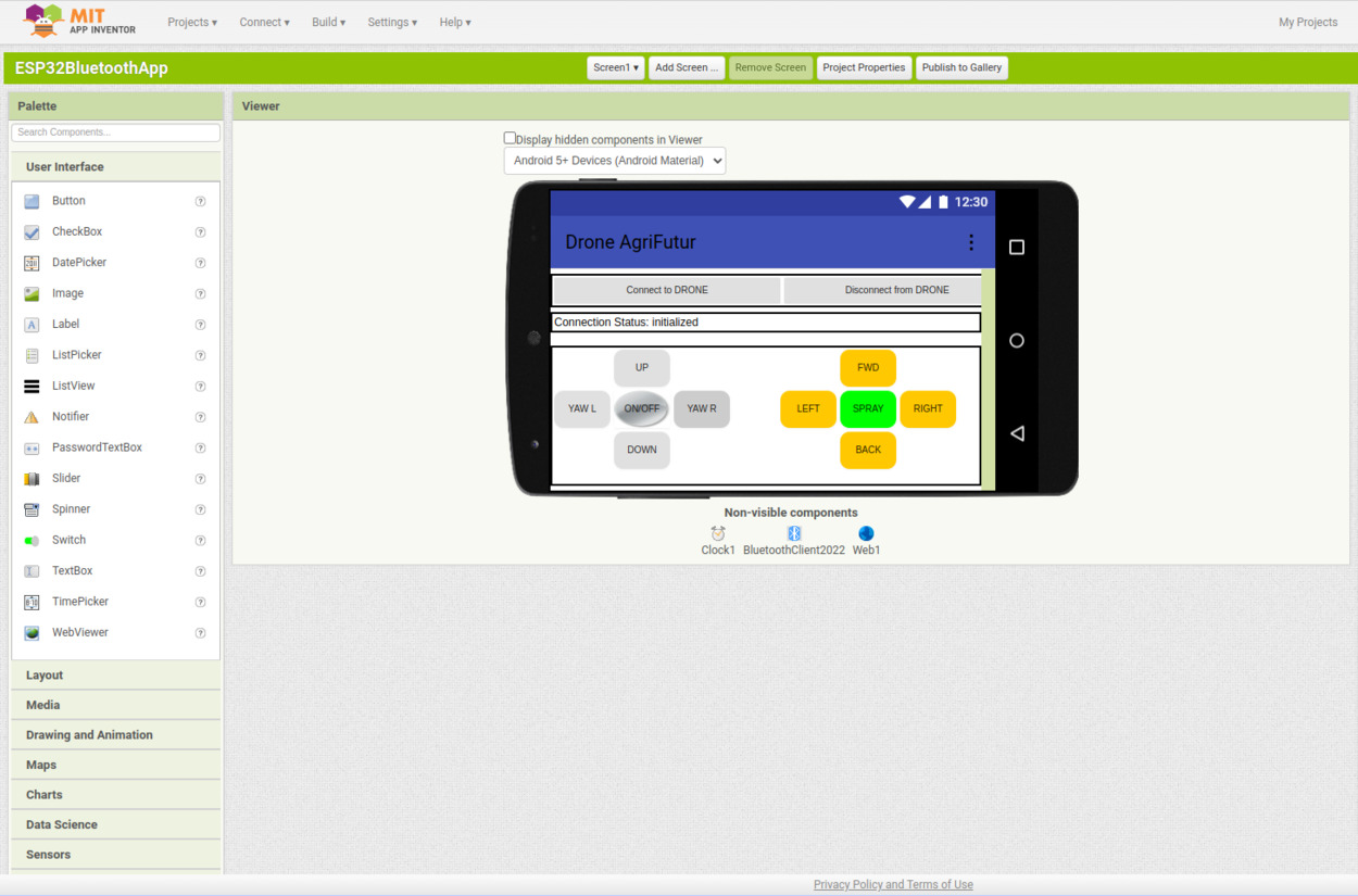
Flight commands
Below is a description of the commands
Left pad:
- Up (UP): to go straight up in level flight
- Down (DOWN): to go straight down in level flight
- Yaw Left (YAW L): to turn (yaw) the drone leftwards in level flight
- Yaw Right (YAW R): to turn (yaw) the drone rightward in level flight
Right pad:
- Forward (FWD): to tilt the drone forward and fly ahead
- Backward (BACK): to tilt the drone backward and fly in reverse
- Left (LEFT): to tilt the drone to the left and bank left in flight
- Right (RIGHT): to tilt the drone to the right and bank right in flight
Those are the main flight controls. Now lets dive in to how the app itself was programmed.
Code blocks
There three main sections to the code blocks written in the app:
- Initialization: these blocks deal with initalizing the app and connecting the bluetooth.
- Controls: these blocks deal with a button press on the screen and send a letter of bluetooth serial to the drone
- ON/OFF: this block deals with turning the drone on and off and sending it the command to hover.
We will discuss each block in detail below.
Initialization code blocks
Details for these code blocks are provided in the image below.

Description of the code blocks seen on the left:
- The top left code block is executed when the screen is initialized and asks permission to connect to bluetooth.
- The second left code block populates a list of the possible bluetooth signals to connect with that are in range
- The third left code block is initialized when the user picks a connection
- The fourth left (bottom left) code block changes the label of the bluetooth connection to connected or disconnected based on its status.
Description of the code blocks seen on the right:
- The top right code block is an error handler that notifies the user if the bluetooth disconnects (on the phone side) or another error occurs.
- The middle right code block is used to disconnect from the bluetooth.
- The bottom right code block handles a bluetooth client error (if there is a disconnection from the drone side).
Next we will discuss the control blocks.
Control code blocks
Details for the control blocks are shown in the image below.

As can be seen each block is the same and deals with two cases for each button:
- Touch Down (left column): is initialized when the user presses on the button, it will send a letter over bluetooth serial that corresponds to the button touched (U, D, F, B, L, R, l, r)
- Touch Up (right column): is initialized when the user lifts their finger off the button. In all cases, the app will send the number “0” over bluetooth serial. Which tells the drone to hover and auto-level.
Next we will discuss the ON/OFF control blocks.
ON/OFF code blocks
The ON/OFF (I/O) code block is shown at the bottom of the following image.

As can be seen, this code block deals with the case when the ON/OFF button is clicked. When its clicked the bluetooth serial is initialized, the command “I” or “O” are sent (depending on the state of the image that is being displayed with record_off.jpg is default). Lastly, the image is updated to show the ON/OFF button as either red or the default off.